12. Hardware Guide
This Hardware Guide provides information about the features, connectors and signals available on the PX30-uQ7 module.
12.1. Q7 Implementation
Q7 has mandatory and optional features. Following table shows the feature set of the PX30-uQ7 module compared to the minimum ARM/RISC based and maximum configuration according to the Q7 standard.
System I/O Interface |
Q7 Minimum |
PX30-uQ7 |
Q7 Maximum |
|---|---|---|---|
PCI Express lanes |
0 |
0 |
4 |
Serial ATA channels |
0 |
0 |
2 |
USB 2.0 ports |
1 |
4 |
8 |
USB 3.0 ports |
0 |
0 |
3 |
LVDS channels |
0 |
1 |
2 |
Embedded DisplayPort |
0 |
0 |
1 |
MIPI-CSI |
0 |
1 |
2 |
HDMI |
0 |
0 |
1 |
High Definition Audio / AC’97 / I2S |
0 |
1 |
1 |
Ethernet 10/100/Gigabit |
0 |
1x 100Mbps |
1x Gigabit |
UART |
0 |
1 (+1 shared with GPIO) |
1 |
GPIO |
0 |
8 |
8 |
Secure Digital I/O |
0 |
1 |
1 |
System Management Bus |
0 |
0 |
1 |
I²C Bus |
1 |
3 |
4 |
SPI Bus |
0 |
1 |
1 |
CAN Bus |
0 |
1 |
1 |
Watchdog Trigger |
1 |
1 |
1 |
Power Button |
1 |
1 |
1 |
Power Good |
1 |
1 |
1 |
Reset Button |
1 |
1 |
1 |
LID Button |
0 |
1 |
1 |
Sleep Button |
0 |
1 |
1 |
Suspend to RAM (S3 mode) |
0 |
1 |
1 |
Wake |
0 |
1 |
1 |
Battery low alarm |
0 |
1 |
1 |
Thermal control |
0 |
1 |
1 |
FAN control |
0 |
1 |
1 |
Note
The PX30-uQ7 module is available in different variants. This document describes the maximum configuration. For details about orderable variants please refer to the order-code document.
Note
Not all interfaces are available at the same time as they might conflict with others. E.g. it is not possible to have LVDS channels and MIPI-DSI at the same time.
12.2. Q7 Connector Pinout
The following table shows the signals on the edge connector of the PX30-uQ7 module.
Empty cells are not connected (NC) pins.
Pin |
Signal |
Pin |
Signal |
|---|---|---|---|
1 |
GND |
2 |
GND |
3 |
4 |
||
5 |
6 |
||
7 |
GBE_LINK# |
8 |
GBE_LINK1000# |
9 |
GBE_MDI1- |
10 |
GBE_MDIO0- |
11 |
GBE_MDI1+ |
12 |
GBE_MDIO0+ |
13 |
GBE_LINK# |
14 |
GBE_ACT# |
15 |
GBE_CTRFF |
16 |
SUS_S5# |
17 |
WAKE# |
18 |
SUS_S3# |
19 |
GP0 |
20 |
PWRBTN# |
21 |
SLP_BTN# |
22 |
LID_BTN# |
23 |
GND |
24 |
GND |
25 |
GND |
26 |
PWGIN |
27 |
BATLOW# |
28 |
RSTBTN# |
29 |
30 |
||
31 |
32 |
||
33 |
34 |
GND |
|
35 |
36 |
||
37 |
38 |
||
39 |
GND |
40 |
GND |
41 |
BIOS_DISABLE# / BOOT_ALT# |
42 |
SDIO_CLK# |
43 |
SDIO_CD# |
44 |
SDIO_LED |
45 |
SDIO_CMD |
46 |
SDIO_WP |
47 |
SDIO_PWR# |
48 |
SDIO_DAT1 |
49 |
SDIO_DAT0 |
50 |
SDIO_DAT3 |
51 |
SDIO_DAT2 |
52 |
|
53 |
54 |
||
55 |
56 |
||
57 |
GND |
58 |
GND |
59 |
I2S_WS |
60 |
|
61 |
I2S_RST# |
62 |
|
63 |
I2S_CLK |
64 |
|
65 |
I2S_SDI |
66 |
GP0_I2C_CLK |
67 |
I2S_SDO |
68 |
GP0_I2C_DAT |
69 |
70 |
WDTRIG# |
|
71 |
THRMTRIP# |
72 |
WDOUT |
73 |
GND |
74 |
GND |
75 |
76 |
||
77 |
78 |
||
79 |
80 |
||
81 |
82 |
||
83 |
84 |
||
85 |
USB_OC# |
86 |
USB_OC# |
87 |
USB_P3- |
88 |
USB_P2- |
89 |
USB_P3+ |
90 |
USB_P2+ |
91 |
USB_VBUS |
92 |
USB_ID |
93 |
USB_P1- |
94 |
USB_P0- |
95 |
USB_P1+ |
96 |
USB_P0+ |
97 |
GND |
98 |
GND |
99 |
LVDS_A0+/DSI_D0+ |
100 |
CSI_D0+ |
101 |
LVDS_A0-/DSI_D0- |
102 |
CSI_D0- |
103 |
LVDS_A1+/DSI_D1+ |
104 |
CSI_D1+ |
105 |
LVDS_A1-/DSI_D1- |
106 |
CSI_D1- |
107 |
LVDS_A2+/DSI_D2+ |
108 |
CSI_D2+ |
109 |
LVDS_A2-/DSI_D2- |
110 |
CSI_D2- |
111 |
LVDS_PPEN |
112 |
LVDS_BLEN |
113 |
LVDS_A3+/DSI_D3+ |
114 |
CSI_D3+ |
115 |
LVDS_A3-/DSI_D3- |
116 |
CSI_D3- |
117 |
GND |
118 |
GND |
119 |
LVDS_A_CLK+/DSI_CLK+ |
120 |
CSI_CLK+ |
121 |
LVDS_A_CLK-/DSI_CLK- |
122 |
CSI_CLK- |
123 |
LVDS_BLT_CTRL / GP_PWM_OUT0 |
124 |
|
125 |
GP2_I2C_DAT / LVDS_DID_DAT |
126 |
LVDS_BLC_DAT |
127 |
GP2_I2C_CLK / LVDS_DID_CLK |
128 |
LVDS_BLC_CLK |
129 |
CAN0_TX |
130 |
CAN0_RX |
131 |
132 |
||
133 |
134 |
||
135 |
GND |
136 |
GND |
137 |
138 |
||
139 |
140 |
||
141 |
GND |
142 |
GND |
143 |
144 |
||
145 |
146 |
||
147 |
GND |
148 |
GND |
149 |
150 |
||
151 |
152 |
||
153 |
154 |
||
155 |
156 |
||
157 |
158 |
||
159 |
GND |
160 |
GND |
161 |
162 |
||
163 |
164 |
||
165 |
GND |
166 |
GND |
167 |
168 |
||
169 |
170 |
||
171 |
UART0_TX |
172 |
UART0_RTS# |
173 |
174 |
||
175 |
176 |
||
177 |
UART0_RX |
178 |
UART0_CTS# |
179 |
180 |
||
181 |
182 |
||
183 |
GND |
184 |
GND |
185 |
GPIO0 |
186 |
GPIO1 |
187 |
GPIO2 |
188 |
GPIO3 |
189 |
GPIO4 |
190 |
GPIO5 / UART1_TX |
191 |
GPIO6 / UART1_RX |
192 |
GPIO7 |
193 |
VCC_BAT |
194 |
SPKR / GP_PWM_OUT2 |
195 |
FAN_TACHOIN / GP_TIMER_IN |
196 |
FAN_PWMOUT / GP_PWM_OUT1 |
197 |
GND |
198 |
GND |
199 |
SPI_MOSI |
200 |
SPI_CS0# |
201 |
SPI_MISO |
202 |
SPI_CS1# |
203 |
SPI_SCK |
204 |
MFG_BIOS_DISABLE# |
205 |
206 |
||
207 |
208 |
UPDI_UART_TX |
|
209 |
UPDI_UART_RX |
210 |
|
211 |
212 |
||
213 |
214 |
||
215 |
216 |
||
217 |
218 |
||
219 |
VCC |
220 |
VCC |
221 |
VCC |
222 |
VCC |
223 |
VCC |
224 |
VCC |
225 |
VCC |
226 |
VCC |
227 |
VCC |
228 |
VCC |
229 |
VCC |
230 |
VCC |
12.3. Signal Details
12.3.1. Ethernet
Q7 Signal |
Type |
Signal Level |
Description |
|---|---|---|---|
GBE_MDI[0:1]+ GBE_MDI[0:1]- |
I/O |
Analog |
Fast Ethernet Controller: Media Dependent Interface Differential Pairs 0,1. The MDI can operate in 100 and 10 Mbit/sec modes |
GBE_ACT# |
OC |
3.3V |
Ethernet Controller activity indicator, active low |
GBE_LINK# |
OC |
3.3V |
Ethernet Controller link indicator, active low |
GBE_LINK100# |
OC |
3.3V |
Internally connected to GBE_LINK# |
GBE_CTREF |
REF |
Analog |
Center Tap Voltage |
12.3.2. USB
Q7 Signal |
Type |
Signal Level |
Description |
|---|---|---|---|
USB_P[0:2]+ USB_P[0:2]- |
I/O |
USB |
High speed universal Serial Bus Port 0, 1, 2 differential pairs |
USB_OC# |
I |
3.3V |
Over current detect input. The baseboard can signal an USB overcurrent condition by pulling this pin low. |
USB_ID |
I |
3.3V |
Configures the mode of the USB Port 1. If the signal is |
USB_VBUS |
I |
5.0V |
USB VBUS pin, 5V tolerant |
12.3.3. SDIO
Q7 Signal |
Type |
Signal Level |
Description |
|---|---|---|---|
SDIO_CD# |
I |
3.3V |
SDIO Card Detect. This signal indicates when a SDIO/MMC card is present |
SDIO_CLK |
O |
3.3V |
SDIO Clock |
SDIO_CMD |
I/O |
3.3V |
SDIO Command/Response |
SDIO_LED |
O |
3.3V |
SDIO LED. Used to drive an external LED to indicate transfers on the bus |
SDIO_WP |
I |
3.3V |
SDIO Write Protect |
SDIO_PWR# |
O |
3.3V |
SDIO Power Enable. This signal is used to enable the power being supplied to a SD/MMC card device |
SDIO_DAT0-4 |
I/O |
3.3V |
SDIO Data lines |
12.3.4. I2C
Q7 Signal |
Type |
Signal Level |
Description |
|---|---|---|---|
Q7_I2C_CLK |
O |
3.3V |
I2C bus clock line connected to PX30 |
Q7_I2C_DAT |
I/O |
3.3V |
I2C bus data line connected to PX30 |
LVDS_DID_CLK /GP2_I2C_CLK |
O |
3.3V |
I2C bus clock line connected to PX30, Secure Element, STM32, Attiny and Video connector |
LVDS_DID_DAT /GP2_I2C_DAT |
I/O |
3.3V |
I2C bus data line connected to PX30, Secure Element, STM32, Attiny and Video connector |
LVDS_BLC_DAT |
O |
3.3V |
I2C bus clock line connected to PX30, Video connector and baseboard EEPROM |
LVDS_BLC_CLK |
I/O |
3.3V |
I2C bus data line connected to PX30, Video connector and baseboard EEPROM |
12.3.5. I2S
Q7 Signal |
Type |
Signal Level |
Description |
|---|---|---|---|
I2S_RST# |
O |
3.3V |
I2S Codec Reset |
I2S_WS |
O |
3.3V |
I2S Word Select |
I2S_CLK |
O |
3.3V |
I2S Serial Data Clock |
I2S_SDO |
O |
3.3V |
I2S Serial Data Output |
I2S_SDI |
I |
3.3V |
I2S Serial Data Input |
12.3.6. Video
The Q7 LVDS_A pins support LVDS and MIDI-DSI. LVDS and MIPI-DSI signals are electrically compatible in the sense that nothing will be damaged, but are not defined in the Qseven standard.
The MIPI-DSI specifications are:
MIPI DSI D-PHY v1.0
Up to four data lates
Up to 1.0 Gbps per lane
The signal mapping is shown below:
Q7 Signal |
Function 1 |
Function 2 |
|---|---|---|
LVDS_A0_P |
LVDS_A0+ |
DSI_D0+ |
LVDS_A0_N |
LVDS_A0- |
DSI_D0- |
LVDS_A1_P |
LVDS_A0+ |
DSI_D1+ |
LVDS_A1_N |
LVDS_A1- |
DSI_D1- |
LVDS_A2_P |
LVDS_A2+ |
DSI_D2+ |
LVDS_A2_N |
LVDS_A2- |
DSI_D2- |
LVDS_A3_P |
LVDS_A3+ |
DSI_D3+ |
LVDS_A3_N |
LVDS_A3- |
DSI_D3- |
LVDS_A_CLK_P |
LVDS_A_CLK+ |
DSI_CLK+ |
LVDS_A_CLK_N |
LVDS_A_CLK- |
DSI_CLK- |
The Q7 LVDS_B pins are used as MIPI-CSI. The specifications are:
MIPI CSI D-PHY v1.0
Up to four data lanes
Up to 1.0 Gbps per lane
The signal mapping is shown below:
Q7 Signal |
Function |
|---|---|
LVDS_B0_P |
CSI_D0+ |
LVDS_B0_N |
CSI_D0- |
LVDS_B1_P |
CSI_D1+ |
LVDS_B1_N |
CSI_D1- |
LVDS_B2_P |
CSI_D2+ |
LVDS_B2_N |
CSI_D2- |
LVDS_B3_P |
CSI_D3+ |
LVDS_B3_N |
CSI_D3- |
LVDS_B_CLK_P |
CSI_CLK+ |
LVDS_B_CLK_N |
CSI_CLK- |
12.3.7. GPIO
Q7 Signal |
Type |
Signal Level |
Description |
|---|---|---|---|
GPIO[0-7] |
I/O |
3.3V |
General purpose inputs/outputs 0 to 7 |
12.3.8. CAN
Q7 Signal |
Type |
Signal Level |
Description |
|---|---|---|---|
CAN0_TX |
O |
3.3V |
CAN (Controller Area Network) TX output for CAN Bus channel 0 |
CAN0_RX |
I |
3.3V |
CAN (Controller Area Network) RX input for CAN Bus channel 0 |
12.3.9. SPI
Q7 Signal |
Type |
Signal Level |
Description |
|---|---|---|---|
SPI_MOSI |
O |
3.3V |
Master serial output/Slave serial input signal |
SPI_MISO |
I |
3.3V |
Master serial input/Slave serial output signal |
SPI_SCK |
O |
3.3V |
SPI clock output |
SPI_CS0# |
O |
3.3V |
SPI chip select 0 output |
SPI_CS1# |
O |
3.3V |
SPI chip select 1 output (used when two devices are connected) |
12.3.10. UART
UART0, as specified in the Q7 standard, is implemented including hardware flow
control. This UART shows up in Linux as /dev/ttyS0.
Q7 Signal |
Type |
Signal Level |
Description |
|---|---|---|---|
UART0_TX |
O |
3.3V |
Serial data transmit |
UART0_RX |
I |
3.3V |
Serial data receive |
UART0_CTS# |
I |
3.3V |
Handshake signal: ready to send data |
UART0_RTS# |
O |
3.3V |
Handshake signal: ready to receive data |
A second UART, UART1, can be enabled on the GPIO pins. This UART shows up in Linux
as /dev/ttyS5.
Q7 Signal |
Alternate function |
Type |
Signal Level |
Description |
|---|---|---|---|---|
GPIO5 |
UART1_TX |
O |
3.3V |
Serial data transmit |
GPIO6 |
UART1_RX |
I |
3.3V |
Serial data receive |
12.3.11. Misc
Signal |
Type |
Signal Level |
Description |
|---|---|---|---|
WDTRIG# |
I |
3.3V |
Watchdog trigger signal |
WDOUT |
O |
3.3V |
Watchdog event indicator |
SPKR GP_PWM_OUT2 |
O |
3.3V |
PC speaker (buzzer) output. Alternate function general purpose PWM output |
BIOS_DISABLE# /BOOT_ALT# |
I |
3.3V |
Disables the onboard bootloader and uses the one the SD card instead. If no bootloader is available on the SD card it falls back to USB recovery mode |
THRMTRIP# |
O |
3.3V |
Thermal Trip indicates an overheating condition of the processor. If ‘THRMTRIP#’ goes active the system immediately transitions to the S5 State (Soft Off) |
FAN_PWMOUT /GP_PWM_OUT1 |
O |
3.3V |
PWM output for fan speed control. Alternate function general purpose PWM output. Function based on microcontroller firmware |
FAN_TACHOIN /GP_TIMER_IN |
I |
3.3V |
Fan tachometer input. Alternate function general purpose timer input. Function based on microcontroller firmware |
12.3.12. Power Management
Signal |
Type |
Signal Level |
Description |
|---|---|---|---|
RSTBTN# |
I |
3.3V |
Reset button input. An active low signal resets the module |
BATLOW# |
I |
3.3V |
Battery low input |
WAKE# |
I |
3.3V |
External system wake event. An active low signal wakes the module from a sleep state |
SUS_S3# |
O |
3.3V |
Indicated that the system is in suspend to ram (S3) |
SUS_S5# |
O |
3.3V |
Indicated that the system is in soft-off state (S5) |
SLP_BTN# |
I |
3.3V |
Sleep button. Signals the system with an falling edge to transition into sleep or wake from a sleep state |
LID_BTN# |
I |
3.3V |
LID button. Low active signal to detect a LID switch to transition into sleep or wake from a sleep state |
12.3.13. Power
Signal |
Nominal Input |
Description |
|---|---|---|
VCC |
5V |
Main supply for the module |
VCC_RTC |
3V |
Backup supply for the RTC. If not used it can be left unconnected. Typical current: 1.4uA |
12.4. On-board Devices
12.4.1. Power-Manager
The Rockchip RK809-1 is connected to the CPU via I2C:
RK809-1 Pin |
Function |
CPU Pin |
|---|---|---|
1 |
SCL |
I2C0_SCL_u (ball R21) |
2 |
SDA |
I2C0_SDA_u (ball M21) |
12.4.2. DDR4
Up to 4GB RAM of DDR4-1600
12.4.3. eMMC
eMMC connected through the 8-bit wide SDIO interface EMMC_D on the CPU.
Signal |
CPU Pin |
Linux GPIO # |
|---|---|---|
RESET |
GPIO1_B3 |
43 |
12.4.4. Companion Controller 1
Controller features are implemented by emulating standard ICs. Feature configuration is provided in a table below.
Feature |
CPU Connection |
Emulated IC |
Qseven Pins |
|---|---|---|---|
RTC |
I2C |
ISL1208 |
none |
Temperature sensor and fan controller |
I2C |
AMC6821 |
FAN_TACHOIN, FAN_PWMOUT |
CAN |
USB |
UCAN |
CAN0_TX, CAN0_RX |
See also Section 10.1 Companion Controller 1 (STM32).
12.4.5. Companion Controller 2
Controller features are implemented by emulating standard ICs. Feature configuration is provided in a table below.
Feature |
CPU Connection |
Emulated IC |
Qseven Pins |
|---|---|---|---|
RTC |
I2C |
ISL1208 |
none |
Temperature sensor and fan controller |
I2C |
AMC6821 |
FAN_TACHOIN, FAN_PWMOUT |
See also Section 10.2 Companion Controller 2 (ATtiny).
12.4.6. Ethernet PHY
The Texas Instruments DP83825IRMQR is connected to the CPU via RGMII and MDIO. Further connections are shown below.
PHY signal |
Connected to |
Linux GPIO # |
|---|---|---|
RESET |
CPU pin GPIO3_B0 |
104 |
MDIO |
CPU pin GPIO2_A7 |
71 |
MDC |
CPU pin GPIO2_B1 |
73 |
LED1 |
Qseven GBE_LINK1000 and GBE_LINK100 and GBE_LINK (tied together) |
|
LED2 |
Qseven GBE_ACT |
12.5. Wifi and Bluetooth module
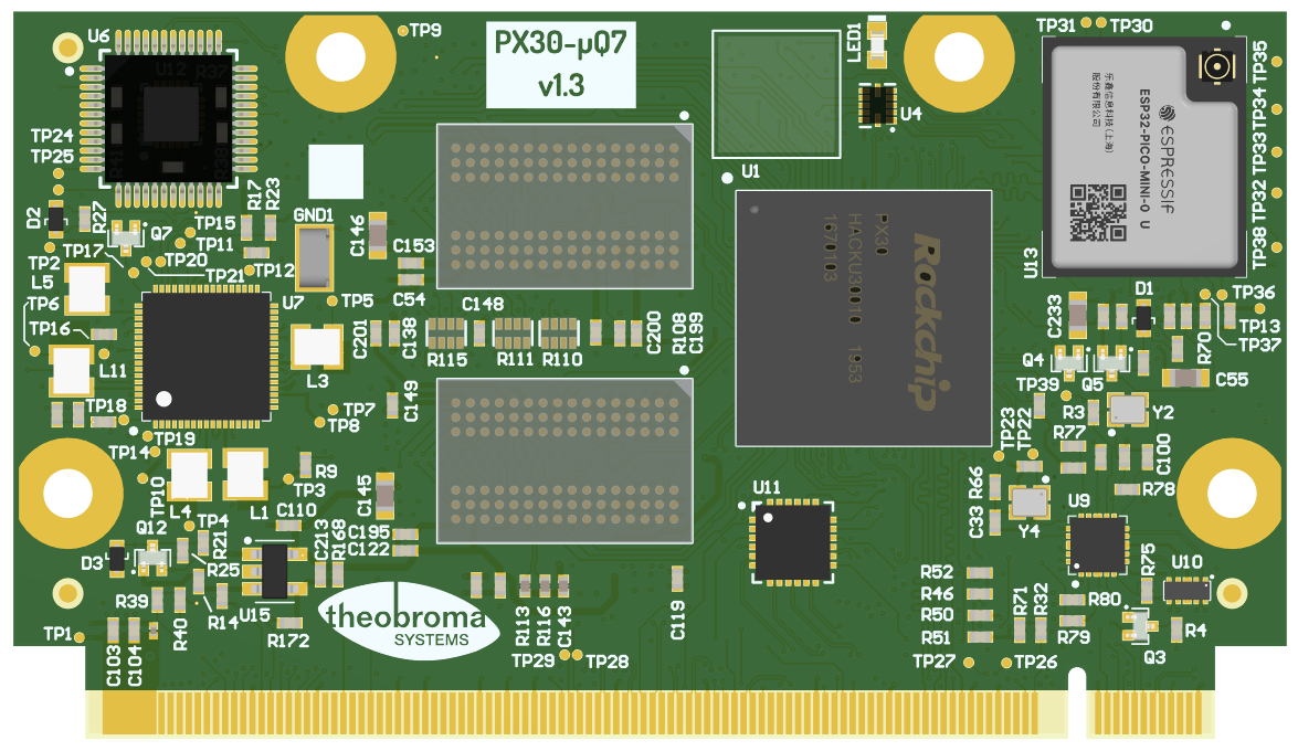
Fig. 12.1 WiFi and Bluetooth module
The WiFi and Bluetooth are part of the ESP32 PICO MINI 02U module on the PX30-uQ7 board. The antenna connector on the module is w.FL type. The firmware running on the ESP32 is flashed in its internal memory and unlike most wireless modules, does not require files to be present in the root filesystem. This also means that a firmware upgrade is slightly more complex since it needs to be flashed (see Section 8.3 Flashing the wifi firmware).
The following pins are used for boot and reset.
ESP32 signal |
CPU Pin |
Linux GPIO # |
|---|---|---|
WiFi_RST |
GPIO2_B0 |
72 |
WiFi_BOOT |
GPIO0_A1 |
1 |
12.5.1. Test points PX30-uQ7 v1.2
Test point |
Connected to |
|---|---|
TP1 |
5V |
TP2 |
VCC_3V3 |
TP3 |
VDD_LOG |
TP4 |
VDD_ARM |
TP5 |
VCC_DDR |
TP6 |
VCC_3V0_1V8 |
TP7 |
VCC_1V8 |
TP8 |
VCC_1V0 |
TP9 |
VCCIO_SD |
TP10 |
VCC_LCD |
TP11 |
1V8_LCD |
TP12 |
VCCA_1V8 |
TP13 |
VCC_eMMC |
TP14 |
PMIC_INT |
TP15 |
PMIC_SLEEP |
TP16 |
VDC |
TP17 |
PMIC_PWRON |
TP18 |
I2C0_SCL |
TP19 |
I2C0_SDA |
TP20 |
PMIC_Xin |
TP21 |
PMIC_Xout |
TP22 |
PX30_Xin |
TP23 |
PX30_Xout |
TP24 |
MCU_UART_TX |
TP25 |
MCU_UART_RX |
TP26 |
Q7_LVDS_DID_CLK |
TP27 |
Q7_LVDS_DID_DAT |
TP28 |
Q7_LVDS_BLC_DAT |
TP29 |
Q7_LVDS_BLC_CLK |
TP30 |
I34 WiFi |
TP31 |
I35 WiFi |
TP32 |
ESP32_TXD0 |
TP33 |
ESP32_RXD0 |
TP34 |
BT_UART_TX |
TP35 |
BT_UART_RX |
TP36 |
BT_RESET |
TP37 |
BT_UART_RTS_n |
TP38 |
BT_UART_CTS_n |
TP39 |
BT_wake_host |
12.6. USB
The PX30-uQ7 CPU has 2 USB 2.0 controllers. A USB 2.0 hub provides two additional USB 2.0 ports for a total of four.
The routing of Qseven signals to CPU and/or hub port is shown below.
Qseven Port # |
Speed |
Connected to |
Notes |
|---|---|---|---|
USB_P0 |
USB 2.0 Hi-Speed |
Hub |
|
USB_P1 |
USB 2.0 Hi-Speed |
CPU |
OTG Port |
USB_P2 |
USB 2.0 Hi-Speed |
Hub |
|
USB_P3 |
USB 2.0 Hi-Speed |
Hub |
The lsusb -t command shows the
USB topology in a tree view and is highly recommended. Its output is discussed below,
for a PX30-uQ7 module without additional devices connected:
- Bus 03.Port 1: Dev 1, Class=root_hub, Driver=ohci-platform/1p, 12M
- Bus 02.Port 1: Dev 1, Class=root_hub, Driver=ehci-platform/1p, 480M
  *  Port 1: Dev 2, If 0, Class=Hub, Driver=hub/4p, 480M
        Port 1: Dev 3, If 0, Class=Mass Storage, Driver=usb-storage, 480M
        Port 3: Dev 4, If 0, Class=Mass Storage, Driver=usb-storage, 480M
        Port 4: Dev 6, If 0, Class=Vendor Specific Class, Driver=ucan, 12M
- Bus 01.Port 1: Dev 1, Class=root hub, Driver=dwc2 1p,  480M
The CAN controller is connected to Port 4 on the hub.
The USB hub can be held in reset, if required. This disables all USB ports connected to the hub. The reset signal routing is shown below:
Hub signal |
CPU Pin |
Linux GPIO # |
|---|---|---|
USBHUB_RESETn |
GPIO0_A5 |
5 |
12.7. Using Qseven Signals as GPIO
Most Qseven signals can be reused as a general purpose I/O pin. The following table shows the mapping and the possible direction as seen from the baseboard.
Qseven Pin |
Signal |
CPU Pin |
Linux GPIO # |
Direction |
|---|---|---|---|---|
16 |
SUS_S5# |
GPIO3_A0 |
96 |
Bidirectional |
17 |
WAKE# |
GPIO1_B6 |
46 |
Input |
18 |
SUS_S3# |
GPIO3_A3 |
99 |
Bidirectional |
19 |
GPO0 |
GPIO2_B3 |
75 |
Bidirectional |
21 |
SLP_BTN# |
GPIO1_B7 |
47 |
Input |
22 |
LID_BTN# |
GPIO3_A6 |
102 |
Bidirectional |
27 |
BATLOW# |
GPIO3_A7 |
103 |
Bidirectional |
42 |
SDIO_CLK# |
GPIO1_D6 |
62 |
Bidirectional |
43 |
SDIO_CD# |
GPIO0_A3 |
3 |
Bidirectional |
44 |
SDIO_LED |
GPIO3_B3 |
107 |
Birectional |
45 |
SDIO_CMD |
GPIO1_D7 |
63 |
Bidirectional |
46 |
SDIO_WP |
GPIO3_B5 |
109 |
Bidirectional |
47 |
SDIO_PWR# |
GPIO3_D3 |
123 |
Bidirectional |
48 |
SDIO_DAT1 |
GPIO1_D3 |
59 |
Bidirectional |
49 |
SDIO_DAT0 |
GPIO1_D2 |
58 |
Bidirectional |
50 |
SDIO_DAT3 |
GPIO1_D5 |
61 |
Bidirectional |
51 |
SDIO_DAT2 |
GPIO1_D4 |
60 |
Bidirectional |
59 |
I2S_WS |
GPIO3_C2 |
114 |
Bidrectional |
63 |
I2S_CLK |
GPIO3_C3 |
115 |
Bidirectional |
65 |
I2S_SDI |
GPIO3_C5 |
117 |
Bidirectional |
66 |
GP0_I2C_CLK |
GPIO2_B7 |
79 |
Bidirectional |
67 |
I2S_SDO |
GPIO3_C4 |
116 |
Bidirectional |
68 |
GP0_I2C_DAT |
GPIO2_C0 |
80 |
Bidirectional |
71 |
THRMTRIP# |
GPIO3_D2 |
122 |
Bidirectional |
111 |
LVDS_PPEN |
GPIO0_A2 |
2 |
Bidirectional |
112 |
LVDS_BLEN |
GPIO0_A0 |
0 |
Bidirectional |
123 |
LVDS_BLT_CTRL / GP_PWM_OUT0 |
GPIO0_B7 |
15 |
Bidirectional |
125 |
GP2_I2C_DAT / LVDS_DID_DAT |
GPIO0_C3 |
19 |
Bidirectional |
127 |
GP2_I2C_CLK / LVDS_DID_CLK |
GPIO0_C2 |
18 |
Bidirectional |
171 |
UART0_TX |
GPIO0_B2 |
10 |
Bidirectional |
172 |
UART0_RTS# |
GPIO0_B5 |
13 |
Bidirectional |
177 |
UART0_RX |
GPIO0_B3 |
11 |
Bidirectional |
178 |
UART0_CTS# |
GPIO0_B4 |
12 |
Bidirectional |
185 |
GPIO0 |
GPIO3_C6 |
118 |
Bidirectional |
186 |
GPIO1 |
GPIO3_D0 |
120 |
Bidirectional |
187 |
GPIO2 |
GPIO3_C7 |
119 |
Bidirectional |
188 |
GPIO3 |
GPIO3_D1 |
121 |
Bidirectional |
189 |
GPIO4 |
GPIO3_C0 |
112 |
Bidirectional |
190 |
GPIO5 |
GPIO3_A2 |
98 |
Bidirectional |
191 |
GPIO6 |
GPIO3_A1 |
97 |
Bidirectional |
192 |
GPIO7 |
GPIO2_B6 |
78 |
Bidirectional |
199 |
SPI_MOSI |
GPIO3_B4 |
108 |
Bidirectional |
200 |
SPI_CS0# |
GPIO3_B1 |
105 |
Bidirectional |
201 |
SPI_MISO |
GPIO3_B6 |
110 |
Bidirectional |
202 |
SPI_CS1# |
GPIO3_B2 |
106 |
Bidirectional |
203 |
SPI_SCK |
GPIO3_B7 |
111 |
Bidirectional |
12.8. Electrical Specification
12.8.1. Power Supply
The power supply requirements are listed in the table below and are identical to the Qseven specification.
Rail |
Description |
Nominal voltage |
Tolerance |
|---|---|---|---|
VCC |
Main power supply |
5V |
4.75 … 5.25V |
VCC_RTC |
Backup battery |
3V |
2.4 … 3.3V |
12.9. Mechanical Specification
12.9.1. Module Dimensions
The mechanical dimensions of the module are shown below.

Fig. 12.2 Module dimensions (all values in mm)
12.9.2. Baseboard Dimensions
The mechanical dimensions of the baseboard are conform with the form factor for Mini-ITX and the baseboard can be mounted in a standard Mini-ITX PC Case.