3. Using the EVK
This chapter provides instructions for using the EVK (also called Haikou), such as booting and how to configure and use I/O peripherals (e.g. serial console, Ethernet).
3.1. Evaluation Board Overview
An overview of the available connectors and devices on the EVK is shown below.
Note
The PX30-uQ7 does not support HDMI and PCIe x4 (they are shown with a * in the next figure).
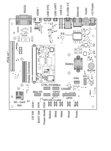
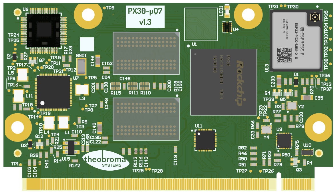
Fig. 3.1 The baseboard with PX30-uQ7 module
(connectors marked with a * are not supported)
3.2. Power Supply
The baseboard can operate with a single 12V DC power supply.

Fig. 3.2 12V Power connector
Power can be controlled manually from the board using the Power control buttons
and switches, located on the lower right side of the board (see Section 3.1 Evaluation Board Overview).
Depending on the setting of Power Mode (Normally On / Normally Off) switch, the board will boot as soon as it receives power.
3.4. CPU Fan
Operation in high environmental temperatures may require a CPU fan. The fan connector is located next to the bottom right corner of the Q7 expansion area.
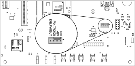
Fig. 3.3 Fan connector
Note
The fan is only necessary in high ambient temperatures. Under normal conditions, the PX30-uQ7 operates passively cooled.
3.5. Boot Order
The used boot order of the PX30-uQ7 module depends on the value of the BIOS_DISABLE# signal.
On the Haikou baseboard, this signal can be set using a slider switch (BOOT SW), with the two positions
labeled Normal Boot, and BIOS Disable.
As shown in the table below, the BIOS Disable position disables the eMMC storage device:
Normal Boot |
BIOS Disable |
|
|---|---|---|
1 |
eMMC storage |
SD card |
2 |
SD card |
USB loader |
3 |
USB loader |
If no bootloader is found on any storage device, the PX30-uQ7 module will go into USB loader mode, showing up as a USB device on the USB-OTG port.
The electrical state of the BIOS_DISABLE# signal for both slider positions is shown below:
Slider Position |
|
|---|---|
Normal Boot |
Floating (on-module pull-up to 3.3V) |
BIOS Disable |
GND |
3.6. USB Serial Console
The evaluation board contains an on-board Silicon Labs CP2102N USB-serial converter.
Connect the included Micro-USB cable to the Micro-USB jack labeled USB-UART Bridge:
Fig. 3.4 USB UART
The serial converter does not require additional drivers on Windows and Linux.
For macOS, drivers are available from Silicon Labs: https://www.silabs.com/products/development-tools/software/usb-to-uart-bridge-vcp-drivers
The PX30-uQ7 module has two external UARTs:
UART0 is, by default, used for the serial console for interactive login.
UART1 is unused by default and can be freely used for machine-to-machine communications or other purposes.
The switch UART0 / UART1 cross-switches UART0 and UART1 between the RS232 / RS485 jack and the onboard
USB-serial converter:
Switch Position |
|
USB-serial converter connected to: |
|---|---|---|
|
UART0 (interactive console) |
UART1 |
|
UART1 |
UART0 (interactive console) |
For interactive login through the USB-serial converter, make sure the switch is on the
UART1 position.
Note
UART1 is the name of the UART exposed on the Haikou baseboard. It is actually
connected to the UART5 controller on the PX30 SoC.
Incidentially, UART0 on Haikou is connected to the UART0 controller on the PX30 SoC.
Picocom can be used to connect via the serial line (assuming the USB-serial converter is USB0):
picocom -b 115200 /dev/ttyUSB0
Note
Make sure to disable software flow-control (XON/XOFF). Otherwise serial input may not be recognized.
After system boot-up, the login console appears on the terminal:
px30-uq7 login:
You can log in as root with password root.
3.7. RS-232 and RS-485
To connect via RS-232 or RS-485, connect to the RS232 / RS485 jack on the base
board.
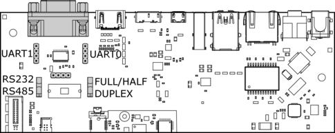
Fig. 3.5 RS-232 connector
The switch labeled RS-232 / RS-485 selects between RS-232 and RS-485 mode on the jack.
In RS-485 mode, the switch labeled Full Duplex / Half Duplex selects full- or half-duplex mode,
respectively. It has no effect in RS-232 mode, which is always full-duplex.
3.8. TTL UART
UART0 and UART1 are also available through the pin headers P12 UART0 and P30 UART1
next to the RS232 / RS485 jack. The signal level is 3.3V.
3.9. Ethernet
The PX30-uQ7 has built-in Fast Ethernet (100Mbit/s) routed to a standard RJ-45 jack on the evaluation board.

Fig. 3.6 Ethernet jack
The SD card that is shipped with the EVK is configured to automatically retrieve an IP address via DHCP and provides SSH login on port 22.
3.10. SD-Card
The PX30-uQ7 supports UHS SD cards and maximum writing speed on the SD card is 50MB/s. The practical writing and reading speeds depend on the capabilities of the inserted SD card.
Fig. 3.7 SD card reader
3.11. USB Interfaces
The PX30-uQ7 provides four USB ports:
1x USB 2.0 OTG
3x USB 2.0 Host

Fig. 3.8 USB 2.0 OTG port (dual-role port: can be used as a host or device interface)
Fig. 3.9 USB 2.0 host ports
3.11.1. Connecting an External USB Drive
To connect a USB drive, plug it into one of the USB ports. The system should recognize the drive immediately. Check the kernel log to find the device name:
dmesg -f
You will be able to mount its partitions (assuming mapping to /dev/sdb1):
mkdir /mnt/usb1
mount /dev/sdb1 /mnt/usb1
ls /mnt/usb1
3.12. Display and Camera
The PX30-uQ7 supports display output on the LVDS A interface and the camera on the LVDS B interface.
For MIPI-DSI and MIPI-CSI, the Qseven LVDS pins are used. Those pins are routed to the
Video connector. This expansion slot uses a PCIe connector as mechanical
connection, which allows easy development of adapter boards for various
different display types.
Qseven Port |
Function |
Alternate Function |
|---|---|---|
LVDS A |
MIPI-DSI |
LVDS |
LVDS B |
MIPI-CSI |
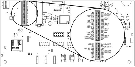
Fig. 3.10 Video connector pinout
The kernel devicetree defines the used display configuration. Example device trees for various output configurations are provided with the EVK software package.
To specify which devicetree should be loaded on boot, edit the configuration variable
FDT in the file /boot/extlinux/extlinux.conf. For example to enable
support for the Haikou Video Demo adapter write:
FDT /boot/px30-ringneck-haikou-video-demo.dtb
Note
For systems using FIT images (such is the case for Yocto images), the
kernel variable should be edited instead:
kernel /fitImage#conf-rockchip_px30-ringneck-haikou-video-demo.dtb
Filename |
Functions |
|---|---|
px30-ringneck-haikou.dtb |
|
px30-ringneck-haikou-video-demo.dtb |
Touchscreen display, camera Requires Video Demo adapter |
3.13. RTC
The PX30-uQ7 contains a real-time clock (RTC) on-module.
Note
This functionality is implemented in the optional Mule companion controller (see Section 12.4.4 Companion Controller 1 and Section 12.4.5 Companion Controller 2).
The RTC is read by the kernel on boot-up and used to set the system clock.
To check the RTC value, use hwclock:
hwclock
Thu 22 Oct 2022 01:49:20 PM CEST  -0.826662 seconds
The RTC will be automatically set to the system clock on shutdown, so you can set the system clock using the date command and reboot to update the RTC:
date --set 2022-10-22
date --set 04:12:33
You can also update the RTC immediately, again with hwclock:
hwclock -w
3.14. SPI and I2C
SPI and I2C interfaces are both available on the pin header labeled SPI+I2C+1-Wire.
The PX30-uQ7 does not support 1-Wire.
Additional I2C buses are available on the SMBUS header.
Note that SMB_DAT, SMB_CLK, SMB_ALERT# are not supported
by the PX30-uQ7 module (shown in thin font in Fig. 3.12).
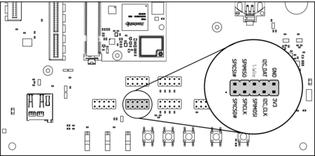
Fig. 3.11 I2C and SPI header
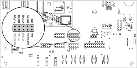
Fig. 3.12 SMBUS header
For I2C, the i2c-tools package is available in Debian:
apt-get install i2c-tools
3.14.1. Linux I2C Bus Numbering
Linux identifies each I2C bus by a bus number. The table below shows the mapping between Q7 names, Linux bus number and EVK header.
Q7 signals |
Linux bus # |
Haikou Header(s) |
Label on Haikou Header |
|---|---|---|---|
GP2_I2C_DAT/LVDS_DID_DAT GP2_I2C_CLK/LVDS_DID_CLK |
1 |
|
|
GP0_I2C_DAT GP0_I2C_CLK |
2 |
|
|
eDP0_HPD#/LVDS_BLC_DAT eDP1_HPD#/LVDS_BLC_CLK |
3 |
|
|
The other I2C buses (as reported by i2cdetect -l) are internal to the
module and not routed to the Q7 connector.
3.15. GPIOs
Eight GPIOs are provided on the pin header labeled GPIO.
The location on the board is displayed below:
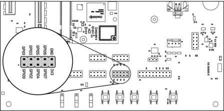
Fig. 3.13 GPIO header
The GPIO numbers printed on the board refer to numbers used in the Qseven specification.
They are different than the ones used in Linux via /sys/class/gpio.
The mapping is shown in the following table:
Q7 signal |
CPU pin |
Linux GPIO # |
|---|---|---|
GPIO0 |
GPIO3_C6 |
118 |
GPIO1 |
GPIO3_D0 |
120 |
GPIO2 |
GPIO3_C7 |
119 |
GPIO3 |
GPIO3_D1 |
121 |
GPIO4 |
GPIO3_C0 |
112 |
GPIO5 |
GPIO3_A2 |
98 |
GPIO6 |
GPIO3_A1 |
97 |
GPIO7 |
GPIO2_B6 |
78 |
To calculate the Linux GPIO # for CPU pins that are not listed in this table, use the following formula:
n = (block_number * 32) + (sub_block_number * 8) + index
Where:
block_number… index of the block numbersub_block_number… the alphabetical index of the block name, minus 1index… the pin number within the block
Example:
GPIO3_C6 -> (3 * 32) + (2 * 8) + 6 = 118
To enable a GPIO, write the Linux GPIO # to the special export file:
$ echo 118 > /sys/class/gpio/export
$ cat /sys/class/gpio/gpio118/direction
in
$ cat /sys/class/gpio/gpio118/value
0
To set the direction to output, write out in the GPIO’s direction file:
$ echo out > /sys/class/gpio/gpio118/direction
$ echo 1 > /sys/class/gpio/gpio118/value
The GPIO will be set to a value of 1 (high at 3.3V).
3.16. Audio
The board provides two audio connectors for input and output.
Line-in is on top and Headphones is on bottom of the audio connector.
Note
The codec on the Haikou baseboard only supports a sample rate 48kHz . This restriction only applies to this specific codec on the Haikou baseboard.
The I2S bus on the PX30-uQ7 module supports a sample rate up to 192kHz.

Fig. 3.14 Audio input/output port
Additionally, an expansion connector for I2S audio is available on the bottom row of the board:
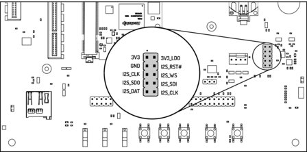
Fig. 3.15 Connecting to the audio expansion connector
3.17. CAN Bus
The board provides a CAN connector on the bottom row.
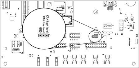
Fig. 3.16 CAN header
Note
CAN feature is only available on PX30-uQ7 module with an STM32, see (Section 12.4.4 Companion Controller 1).
3.18. CTRL I/O Connector
The board provides signals for watchdog trigger in- and output, SoM PMIC power-on input, reset and external display power enable.
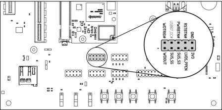
Fig. 3.17 CTRL I/O header
3.19. MISC Connector
The board provides signals for thermal overheat of external hardware and the processor, utility signals for SD and GPIO0.
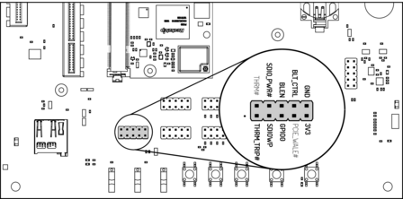
Fig. 3.18 MISC header
3.20. JTAG Connector
The board provides UPDI signals on the JTAG connector. The PX30-uQ7 does not support JTAG, but the ATtiny (see Section 12.4.5 Companion Controller 2) can be flashed over JTAG connector pins.
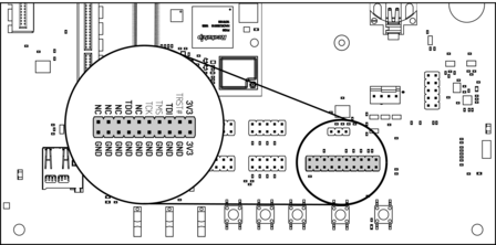
Fig. 3.19 JTAG header
JTAG header |
Function |
|---|---|
TDI |
UPDI-TX |
TDO |
UPDI-RX |