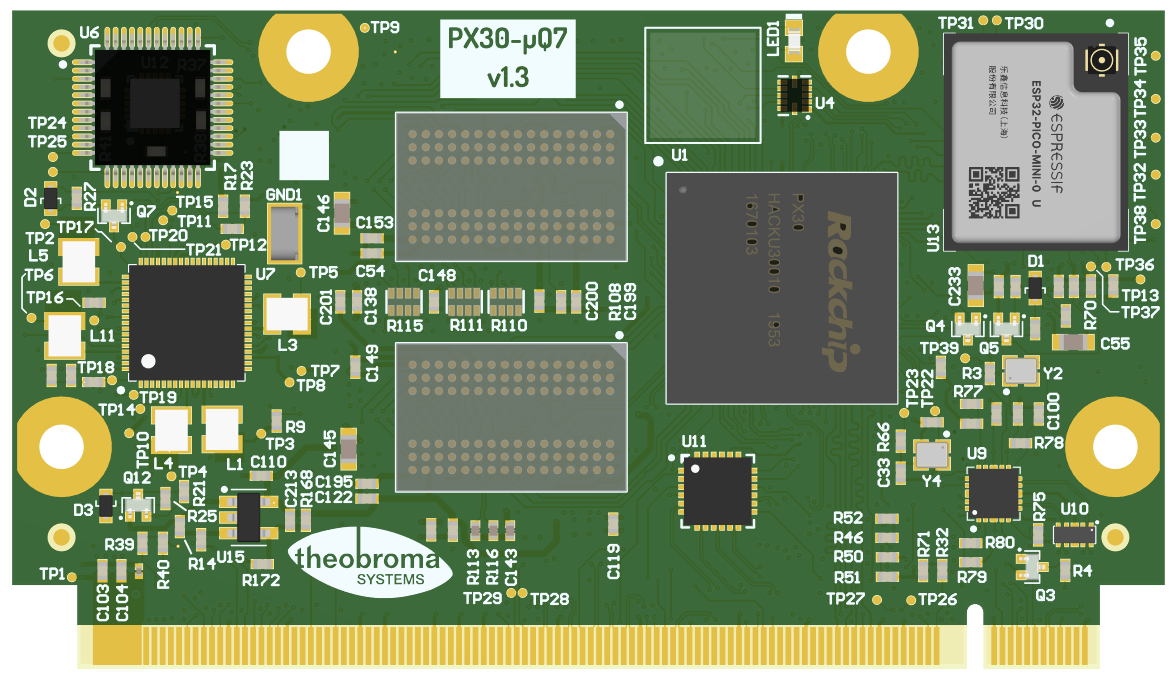
10. Mule Companion Controller
Mule Companion Controller is an on-board microcontroller, that provides additional features to the CPU. Mule is available in two variants:
Companion Controller 1 (STM32)
Companion Controller 2 (ATtiny)
Only one variant can be available on the board.
Both variants support almost the same set of features. The only difference is CAN support.
Feature set and usage manual of both variants are described in subsections below.
10.1. Companion Controller 1 (STM32)
Controller is based on STM32 microcontroller and provides additional features to the CPU, exposed via I2C and USB. It emulates standard ICs and does not need custom drivers on Linux.
Mule STM32 controller supports the following features:
RTC
Temperature sensor
Fan controller
CAN
For hardware details, please refer to Section 12.4.4 Companion Controller 1.
10.1.1. Internal connections
Mule STM32 controller is connected to SoC via I2C, USB and the following pins.
Function |
CPU Pin |
Linux GPIO # |
|---|---|---|
NRST |
GPIO3_A4 |
100 |
BOOT0 |
GPIO3_A5 |
101 |
10.1.2. DFU mode
The USB DFU bootloader application provides access to the internal flash memory of STM32 microcontroller.
To enter DFU mode:
Pull BOOT0 pin high
Cycle reset Mule STM32 using NRST pin
The microcontroller will appear as a new USB device in Linux (vid:pid as 0483:df11)
To return to normal operation, BOOT0 must be pulled low again to not enter DFU mode in the next power-cycle.
10.1.3. Flashing the STM32 firmware
For convenience, mule.sh tool is available for controlling and flashing the
STM32 microcontroller. Executing the script, SoC resets microcontroller into
DFU mode and then uploads the firmware binary to internal STM32 flash memory.
The tool is available here: https://git.theobroma-systems.com/som-tools.git/tree/mule.
To flash STM32 microcontroller using mule.sh, please follow the steps below.
Install
mule.shdependencies according toREADME.mdUpload
mule.shtool andmule.dfufirmware file to a deviceFlash controller using the following command:
sudo ./mule.sh --flash mule.dfu
Note
It is highly recommended that one reboots the main SoC interacting with the companion microcontroller after flashing to make sure device drivers are properly initialized.
10.2. Companion Controller 2 (ATtiny)
Controller is based on ATtiny microcontroller and provides additional features to the CPU, exposed via I2C. This controller is a substitute for first controller, supports the same functions except CAN. As for the first controller, it emulates standard ICs and does not need custom drivers on Linux.
Mule ATtiny controller supports the following features:
RTC
Temperature sensor
Fan controller
For hardware details, please refer to Section 12.4.5 Companion Controller 2.
10.2.1. Internal connections
Mule ATtiny controller is connected to SoC via I2C bus and the following pins.
Function |
CPU Pin |
Linux GPIO # |
|---|---|---|
RST |
GPIO3_A4 |
100 |
BOOT |
GPIO3_A5 |
101 |
10.2.2. Flashloader mode
Flashloader mode allows writing to the internal ATtiny flash memory via I2C.
To enter flashloader mode:
Pull BOOT pin high
Cycle reset ATtiny using RST pin
10.2.3. Flashing the ATtiny firmware
The ATtiny microcontroller can be flashed from SoC through the I2C interface
using i2c-flash tools. Executing the script, SoC resets microcontroller into
flashloader mode and then transfers the binary that will be committed to flash.
Tools are available here: https://git.theobroma-systems.com/som-tools.git/tree/mule-attiny.
To flash ATtiny microcontroller, please follow the steps below.
Setup tool dependencies according to
README.mdFlash controller using the following command:
./i2c_flash -f {firmware.bin} -c 3 -g 5 -b 1 -rc 3 -rg 4
Note
It is highly recommended that one reboots the main SoC interacting with the companion microcontroller after flashing to make sure device drivers are properly initialized.
