3. Using the EVK
This chapter provides instructions for using the EVK, such as booting and how to configure and use I/O peripherals (e.g. serial console, Ethernet).
3.1. Evaluation Board Overview
An overview of the available connectors and devices on the EVK is shown below.
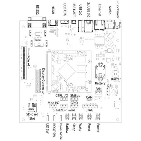
The base board for to RK3399-Q7 module.
3.2. Power Supply
The baseboard can operate with a single 12V DC power supply.

12V Power connector
Power can be controlled manually from the board using the Power control buttons
and switches, located on the lower right side of the board (see 3.1 Evaluation Board Overview).
Depending on the setting of Normally On / Normally Off switch the board will boot as soon as it receives power.
3.3. Control Buttons and Switches
The control buttons provide the following functionality:
Powertoggles the module power supplyResettriggers a module resetBatlow,SleepandWakeare routed to GPIOs on the Q7 module
Several slide switches are located on the lower left:
LIDis routed to a GPIO on the module, simulates lid open/close.Normally On / Normally Off, as described above, sets the state after power loss.BIOS Disable / Normal Bootforces SD card boot or the normal boot order, respectively.
3.4. CPU Fan
Operation in high environmental temperatures may require a CPU fan. The fan connector is located next to the bottom right corner of the Q7 expansion area (see board overview).
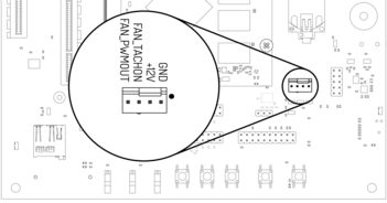
Fan connector
Note
The fan is only necessary in high ambient temperatures. Under normal conditions, the RK3399-Q7 operates passively cooled.
3.5. Boot Order
The used boot order of the RK3399-Q7 module depends on the value of the BIOS_DISABLE# signal.
On the Haikou baseboard, this signal can be set using a slider switch, with the two positions
labeled Normal Boot, and BIOS Disable.
As shown in the table below, the BIOS Disable position disables both on-module storage devices:
| Normal Boot | BIOS Disable | |
|---|---|---|
| 1 | SPI NOR flash | SD card |
| 2 | eMMC storage | USB loader |
| 3 | SD card | |
| 4 | USB loader |
If no bootloader is found on any storage device, the RK3399-Q7 module will go into USB loader mode where it shows up as a USB device on the USB-OTG port.
The electrical state of the BIOS_DISABLE# signal for both slider positions is shown below:
| Slider Position | BIOS_DISABLE# signal |
|---|---|
| Normal Boot | Floating (on-module pull-up to 1.8V) |
| BIOS Disable | GND |
3.6. USB Serial Console
The evaluation board contains an on-board Silicon Labs CP2102N USB-serial converter.
Connect the included Micro-USB cable to the Micro-USB jack labeled USB-UART Bridge:

USB UART
The serial converter does not require additional drivers on Windows and Linux.
For Mac OS, drivers are available from Silicon Labs: http://www.silabs.com/products/development-tools/software/usb-to-uart-bridge-vcp-drivers
The Q7 modules has two external UARTs:
- UART0 is, by default, used for the serial console for interactive login.
- UART1 is unused by default and can be freely used for machine-to-machine communications or other purposes.
The switch UART0 / UART1 cross-switches UART0 and UART1 between the RS232 / RS485 jack and the onboard
USB-serial converter:
| Switch Position | RS232 / RS485 jack connected to: |
USB-serial converter connected to: |
|---|---|---|
UART0 |
UART0 (interactive console) | UART1 |
UART1 |
UART1 | UART0 (interactive console) |
For interactive login through the USB-serial converter, make sure the switch is on the
UART1 position
Picocom can be used to connect via the serial line (assuming the USB-serial converter is USB0):
picocom -b 115200 /dev/ttyUSB0
Note
Make sure to disable software flow-control (XON/XOFF). Otherwise serial input may not be recognized.
After system bootup, the login console appears on the terminal:
rk3399-q7 login:
You can log in as root with password root or as user user with password
user.
3.7. RS-232 and RS-485
To connect via RS-232 or RS-485, connect to the RS232 / RS485 jack on the base
board.

RS-232 connector
The switch labeled RS-232 / RS-485 selects between RS-232 and RS-485 mode on the jack.
In RS-485 mode, the switch labeled Full Duplex / Half Duplex selects full- or half-duplex mode,
respectively. It has no effect in RS-232 mode, which is always full-duplex.
3.8. TTL UART
UART0 and UART1 are also available through the pin headers P12 UART0 and P30 UART1
next to the RS232 / RS485 jack. The signal level is 3.3V.
3.9. Ethernet
The RK3399-Q7 has built-in Gigabit Ethernet routed to a standard jack on the evaluation board.

Ethernet jack
The SD card that is shipped with the EVK is configures to automatically retrieve an IP via DHCP and provides SSH login on port 22.
3.10. USB Interfaces
The RK3399-Q7 provides four USB ports:
- 1x USB 3.0 OTG
- 2x USB 3.0 Host
- 1x USB 2.0 Host

USB 3.0 OTG port (dual-role port: can be used as a host or device interface)

USB 3.0 host ports

USB 2.0 host port
3.10.1. Connecting an External USB Drive
To connect a USB drive, plug it into one of the USB ports. The system should recognize the drive immediately. Check the kernel log to find the device name:
journalctl -k -10
You will be able to mount its partitions (assuming mapping to /dev/sdb1):
mkdir /mnt/usb1
mount /dev/sdb1 /mnt/usb1
ls /mnt/usb1
3.11. Video
The RK3399-Q7 supports video output on HDMI, eDP and MIPI-DSI. Some of these interfaces are muxed on the module.

RK3399-Q7 video muxing
The EVK software will use HDMI as the default video output. Connect a display to the HDMI port and a desktop environment will be shown once booting has finished. Screen resolution will be set based on the display EDID information. Resolutions up to 3840x2160 are supported.

HDMI port
For eDP and MIPI-DSI the Qseven LVDS pins are used which are routed to the
Display connect. This expansion slot uses a PCIe connector as mechanical
connection, which allows easy development of adapter boards for various
different display types.
| Qseven Port | Function | Alternate Function |
|---|---|---|
| LVDS A | MIPI-DSI | eDP |
| LVDS B | MIPI-DSI | MIPI-CSI |
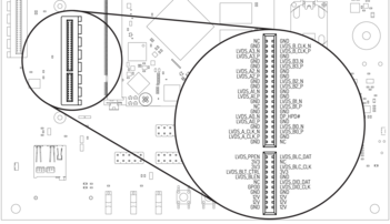
Display connector pinout
The kernel devicetree defines the used display configuration. Example device trees for various output configurations are provided with the EVK software package.
To configure the bootloader which devicetree to load, edit the configuration variable
fdtfile in the file /boot/puma_rk3399/userEnv.txt. For example to enable
DisplayPort write:
fdtfile=rk3399-puma-edp.dtb
| Filename | Display 1 | Display 2 |
|---|---|---|
| rk3399-puma.dtb | HDMI | |
| rk3399-puma-edp.dtb | Display Port on LVDS A | |
| rk3399-puma-mipidsi.dtb | MIPI-DSI on LVDS A | |
| rk3399-puma-hdmi+edp.dtb | HDMI | Display Port on LVDS A |
| rk3399-puma-hdmi+mipidsi.dtb | HDMI | MIPI-DSI on LVDS A |
See https://git.theobroma-systems.com/som-hardware.git/ for video adapter reference designs.
3.12. RTC
the RK3399-Q7 contain a real-time clock (RTC) on-module. The RTC is read by the kernel on bootup and used to set the system clock.
To check the RTC value, use hwclock:
hwclock
Thu 30 Apr 2015 03:51:20 PM CEST  -0.826662 seconds
The RTC will be set automatically to the system clock on shutdown, so you can set the system clock using the date command and reboot to update the RTC:
date --set 2015-04-20
date --set 03:51:30
You can also update the RTC immediately, again with hwclock:
hwclock -v
You can set up an NTP client so the time will always be updated from the Internet. Install the client first:
apt-get install ntp
Feel free to change the /etc/ntp.conf file to use more local time sources
(change servers from pool.ntp.org to use a server from your country, such as
at.pool.ntp.org).
3.13. SPI, I2C and 1-Wire
I2C, 1-wire-bus and SPI interfaces are both available on the connector labeled SPI+I2C+1-Wire.
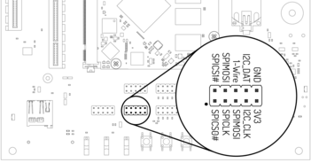
I2C and SPI header
For I2C, there is the package i2c-tools available in Debian:
apt-get install i2c-tools
3.13.1. I2C Example - Using a Touch Keyboard
This example uses the Atmel AT42QT2160 touch keyboard (see datasheet).
Make sure the Linux kernel driver is enable via menuconfig:
make menuconfig
Navigate to Device Drivers -> Input device support -> Keyboards and check the ATMEL AT42QT2160 Touch Sensor Chip. You must recompile the kernel and deploy it to the SD card (see Software Guide).
3.13.2. SMBus
The board provides communication through SMBus. It is basically like I2C with an additional line for interrupt and is used for connecting sensors and power peripherals.
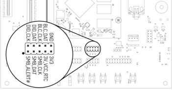
SMBUS header
3.13.3. Linux Bus Numbering
Linux identifies each I2C bus using a bus number. The table below shows the mapping between Q7 names, Linux bus number and EVK header.
| Q7 name | Linux bus # | EVK Header |
|---|---|---|
| GP0_I2C | 4 | SPI+I2C+1-Wire |
| SMB / GP1_I2C | 2 | SMBus |
| GP2_I2C / LVDS_DID | 1 | Display connector |
| LVDS_BLC | 7 | Display connector |
The other I2C buses (as reported by i2cdetect -l) are internal to the module and not routed to the Q7 connector.
3.14. GPIOs
Eight GPIOs are provided on the pin header labeled GPIO.
The location on the board is displayed below:
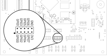
GPIO header
The GPIO numbers printed on the board refer to numbers used in the Qseven specification. They are different than the ones used in Linux via /sys/class/gpio.
The mapping is shown in the following table:
| Qseven signal | CPU pin | Linux GPIO # |
|---|---|---|
| GPIO0 | GPIO4_D4 | 156 |
| GPIO1 | GPIO4_D1 | 153 |
| GPIO2 | GPIO4_D0 | 152 |
| GPIO3 | GPIO4_D5 | 157 |
| GPIO4 | GPIO4_D2 | 154 |
| GPIO5 | GPIO4_C4 | 148 |
| GPIO6 | GPIO4_C3 | 147 |
| GPIO7 | GPIO4_D3 | 155 |
To calculate the Linux GPIO # for CPU pins that are not listed in this table, use the following formula:
n = (block_number * 32) + (sub_block_number * 8) + index
Where:
- block_number: index of the block number
- sub_block_number: the alphabetical index of the block name, minus 1
- index: the pin number within the block
Example:
GPIO4_D4 -> (4 * 32) + (3 * 8) + 4 = 156
To enable a GPIO, write the Linux GPIO # to the special export file:
echo 156 > /sys/class/gpio/export
ls /sys/class/gpio/gpio156
cat /sys/class/gpio/gpio156/direction
in
cat /sys/class/gpio/gpio156/value
0
To set the direction to output, write out in the GPIO’s direction file:
echo out > /sys/class/gpio/gpio156/direction
echo 1 > /sys/class/gpio/gpio156/value
The GPIO will be set to a value of 1 (high at 3.3V).
3.15. Audio
The board provides two audio connectors for input and output.
Line-in is on top and Headphones is on bottom of the audio connector.

Audio input/output port
Additionally, an expansion connector for I2S audio is available on the bottom row of the board:
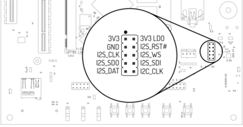
Connecting to the audio expansion connector
3.17. CTRL I/O Connector
The board provides signals for watchdog trigger in- and output, SoM PMIC power-on input, reset and external display power enable.
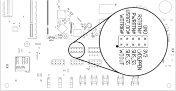
CTRL I/O header
3.18. MISC Connector
The board provides signals for thermal overheat of external hardware and the processor, utility signals for SD and GPIO0.
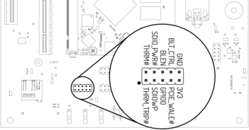
MISC header
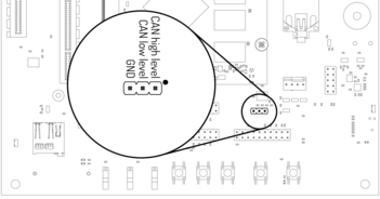
3.19. RF-Module
An additional RF-Module for wireless communication can be soldered on the bottom right of the baseboard.
For more information visit: https://www.theobroma-systems.com/rf-modules-3815